Nyloplast Drain Basin Layout with Minimum Angle Measurement Example Detail
Filename:
Nyloplast Drain Basin Layout with Minimum Angle Measurement Example Detail.dwg
This document is the Nyloplast Drain Basin Layout with Minimum Angle Measurement Example Detail. Illustration with descriptions and directions shown.
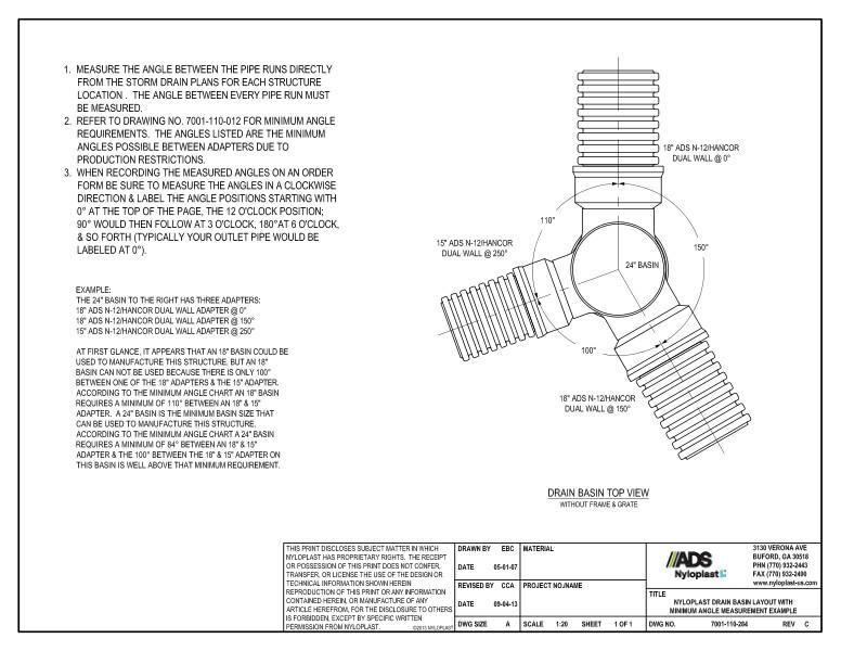
The top view detail shows the various parts and dimensions of the drain basin without the frame or grate. It includes two 18” ADS N-12/Hancor dual walls, 15” ADS N-12/Hancor dual wall and 24” basin.
Directions recommend to measure the angle between the pipe runs directly from the storm drain plans for each structure. The angle between every pipe run must be measured. #2 refers to drawing number 7001-110-012 for minimum angle requirements. #3 says when recording the measured angles on an order form, be sure to measure the angles in a clockwise direction and label the angle positions starting with the 12 o’clock position.
A note states that an 18” basin could be used to manufacture the structure but an 18” basin cannot be used because there is only 100 degrees between one of the 18” adapters and the 15” adapters. Further instructions on how to determine angles is offered.