111G Aircraft Landing Gear Footprint (HP Storm) Detail
Filename:
111G Aircraft Landing Gear Footprint (HP Storm) Detail.dwg
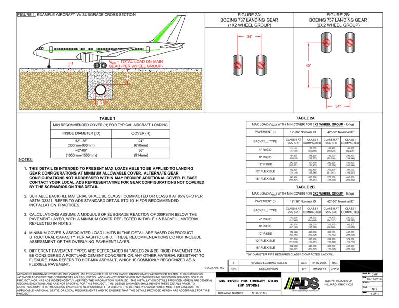
This document is the Aircraft Landing Gear Footprint Detail. A Boeing aircraft with subgrade cross detail and landing gear figures with tables are shown.
The Boeing aircraft with subgrade cross detail illustrates the total load on main gear per wheel group. Figure 2A shows the dimension for a Boeing 737 landing gear, 1x2 wheel group. Figure 2B shows the dimensions for a Boeing 737 landing gear, 2x2 wheel group.
Table 1 is the minimum recommended cover (H) for typical aircraft loading for inside diameter and cover.
Table 2A has the values for maximum load with minimum cover for 1x2 wheel group for pavement and 2 nominal IDs.
Table 2B has the values for maximum load with minimum cover for 2x2 wheel group for pavement and 2 nominal IDs.
Notes state that this detail is intended to present max loads able to be applied to landing gear configurations at minimum allowable cover. Alternate gear configurations may require additional cover. Suitable backfill material is Class I compacted or Class II at 95% SPD per ASTM D2321. Calculations assume a modulus of subgrade reaction of 300PSI/N below pavement layer. Minimum cover and associated load limits are based on product structural capacity per AASHTO LRFD. Rigid pavement can be considered a Portland cement concrete or other material resistant to flexure.