MC-7200 StormTech Technical Specifications
Filename:
MC-7200 StormTech Technical Specifications.pdf
StormTech MC-700 StormTech Chamber system. The specifications state that only chambers that are manufactured by ADS and approved by site engineers will be used. Chambers will meet the requirements of ASTM F2418-16a, Chamber shall be designed, tested and allowable load configurations determined in accordance with ASTM F2787.
Important notes for the bidding and installation of the MC-7200 Chamber System include installation per the StormTech MC-7200 construction guide, backfill methods, foundation and embedment stone recommendations, seating joints, inlet/outlet manifold insertion and notes for construction equipment.
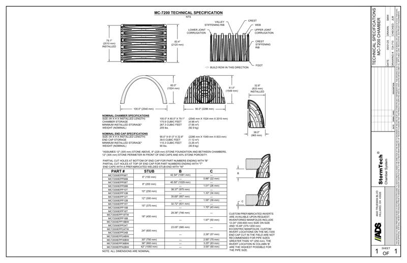
MC-7200 technical detail with chamber specifications, nominal end cap specifications, part numbers and drawings are shown.
An Isolator Row Plus detail diagram, underdrain detail, inserta-TEE side inlet diagram, MC-series end cap insertion detail and 4” PVC inspection port details are included.
StormTech Isolator Row Plus detail diagram shows a cross section of the cover pipe connection to end cap, flamp access pipe install with the MC-7200 chamber, inspection port, flexstorm inserts, sump depth, catch basin HDPE access pipe and geotextile layer between foundation stone and chambers.
The steps under inspection and maintenance require inspection of Isolator Row Plus for sediment, how to clean the Isolator Row Plus using the jetvac process, replacing covers, grates, filters and lids while recording observations and actions and inspection/cleaning basins and manholes upstream from the StormTech system.
A note suggests inspection occur every 6 months during the first year of operation and to adjust schedule based on observations of sediment. A maintenance note asks to conduct jetting and vactoring annually or when maintenance is necessary.
A 4” PVC inspection port detail shows the MC series chamber. The concrete collar, concrete slab, nyloplast inspection port, SDR 35 pipe, inserta TEE and minimum width requirements. A note suggests inspection ports may be connected through any chamber corrugation valley.
An acceptable fill material chart lists material location, descriptions, AASHTO material classifications and compaction/density requirements. A cross-section diagram shows stone, soil and pavement layers with the geotextile and MC-7200 end cap. The cross section detail represents minimum requirements for installation.