Septic Stack Trench Serial Installation Detail
Filename:
Septic Stack Trench Serial Installation Detail.dwg

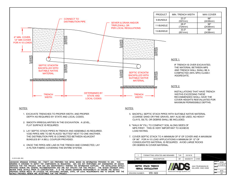
This document is the Septic Stack Trench Serial Installation Detail. A diagram with descriptors and notes explains the septic stack trench. A table is provided.
This Septic Stack Trench diagram shows minimum covers for H-10 loads, sewer & drain and/or triplewall pipe per local regulations, connection to distribution pipe, septic stack backfilled with suitable native material and trench width.
Notes explain installation with directions to excavate trenches to proper width and depth. Smooth irregularities in the excavation because a level/flat surface is required. Lay septic stack pipe in trench and assemble as required. Void pipes are to be placed “butted” next to one another. The distribution pipe is connected between adjacent bundles by a bell coupler. Once pipes are laid in the trench and connected, lay a filter fabric covering the entire system. Backfill septic stack pipes with suitable native material. “Walk in” fill to compact soil along sides of MPS first for load rating. Cover septic stack to a minimum of 6” of cover and a maximum of 96”. For H-10 load applications, a minimum of 12” of consolidated material is required. Avoid large rocks or debris in cover material.
The table provides the specifications for the product, minimum trench width and maximum cover.
If trench is over excavated, the material between MPS and trench wall shall be a compacted Class I aggregate.
Installations that have trench widths exceeding these recommended shall have cover heights re-evaluated for maximum permissible depths.
