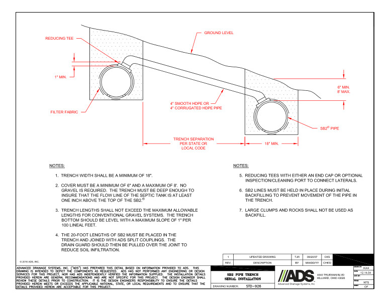
SB2 Pipe Trench Serial Installation Detail
Filename:
SB2 Pipe Trench Serial Installation Detail.pdf

This document is SB2 Pipe Trench Serial Installation Detail. A diagram with descriptors and notes explains the pipe trench.
This pipe trench diagram shows the ground level, reducing Tee, filter fabric, 4” smooth HDPE or 4” corrugated HDPE pipe, trench separation per state or local code, SB2 pipe and various minimum/maximum widths/depths.
Notes explain pipe trench that the width shall be a minimum of 18”. Cover must be a minimum of 6” and maximum of 8”. No gravel required. The trench must be deep enough to ensure that the flow line of the septic tank is at least one inch above the top of the SB2. Trench lengths must not exceed the maximum allowable lengths for conventional gravel systems. The trench bottom should be level with a maximum slope of 1” per 100 lineal feet. The 20 foot lengths of SB2 must be placed in the trench and joined with ADS split couplings. The drain guard should then be pulled over the joint to reduce soil infiltration. Reducing Tees with either plain end caps or optional inspection/cleaning port should be used to connect laterals. SB2 lines should be held in place during initial backfilling to prevent movement of the pipe in the trench. Large clumps and rocks should not be used as backfill.
