TN 6.32-7200 Manifold Sizing Guidance for StormTech Chambers
Filename:
TN 6.32-7200 Manifold Sizing Guidance for StormTech Chambers.pdf
Manifold Sizing for StormTech Chamber Systems.
This technical document summarizes the methods ADS uses for calculating the size and configuration of manifolds for the StormTech chamber system.
StormTech Chamber manifolds are comprised of smooth interior pipes, fittings, injection molded and prefabricated manifold sections that align with the proper spacing of the chamber rows. The use of common pipe components enables the engineer to apply straightforward hydraulic equations to size the manifold system.
The primary manifold design objectives are to convey the peak flows to and from the chamber system without causing an unacceptable backwater and to preclude scour of foundation stone under the chamber system. ADS assumes the maximum allowable water surface elevation is at full storage (top of open graded cover stone). The design engineer may choose to design for a higher maximum water surface elevation. Since the relationship between the inflow hydrographs, outlet control, time to peak and accumulated storage are site specific and complex, ADS assumes that the peak inlet flow occurs when there is no water in the chambers. This is the worst-case condition for scour. ADS assumes that the chambers are full when the peak outlet flow occurs.
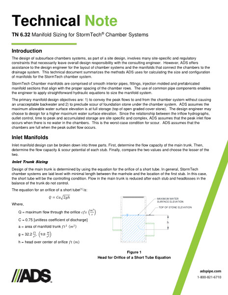
Inlet manifold design can be broken down into three parts. First, determine the flow capacity of the main trunk. Then, determine the flow capacity & scour potential of each stub. Finally, compare the two values and choose the lesser of the two. Inlet trunk sizing, stub sizing are supported with formulas, figures and ratio tables.
The purpose of the outlet manifold “hard-pipe connection(s)” is to ensure that there are free-flooding conditions between the StormTech chambers and the outlet control structure. The outlet manifold must be able to pass the design peak outlet flow rate from the chamber system to the outlet control structure. Formulas, figures and outlet flow tables are included.
In addition to conveying the peak flow rates, StormTech manifolds are designed to distribute water across the chamber system and provide a direct flow path from inlet to outlet. For wider beds, manifold stubs are spaced out over the available rows. Spread configurations help prevent conditions where lateral flow through the embedment stone limits the distribution across the system. Flow path figures and estimated flow rate table are included.